Matrix manipulation can be a bit of a pain, though and getting the manipulation wrong is pretty easy to do. For this reason my initial examples working with the Rift in any language or toolkit always involve rendering a small colored cube of a specific size very close to the viewer. This type of scene serves as a useful test for a variety of ways it's possible to screw up the matrices or their application to the scene.
I'm going to look at why that is, and what the effects of incorrect matrix manipulation look like
As I said I create a simple scene with a small cube. How small is very specific. The size of the cube (the distance from one side to the other) is set to the exact distance between the eyes (the interpupillary distance, or IPD). If we were to make the object smaller than this it would be possible to see both the left side and the right side of the cube at the same time from the respective eyes.
With the size set to the IPD distance it becomes impossible to see two opposing sides of the cube at the same time, because the sides are being viewed edge on.
Virtually any movement left or right will show you one of the side faces though.
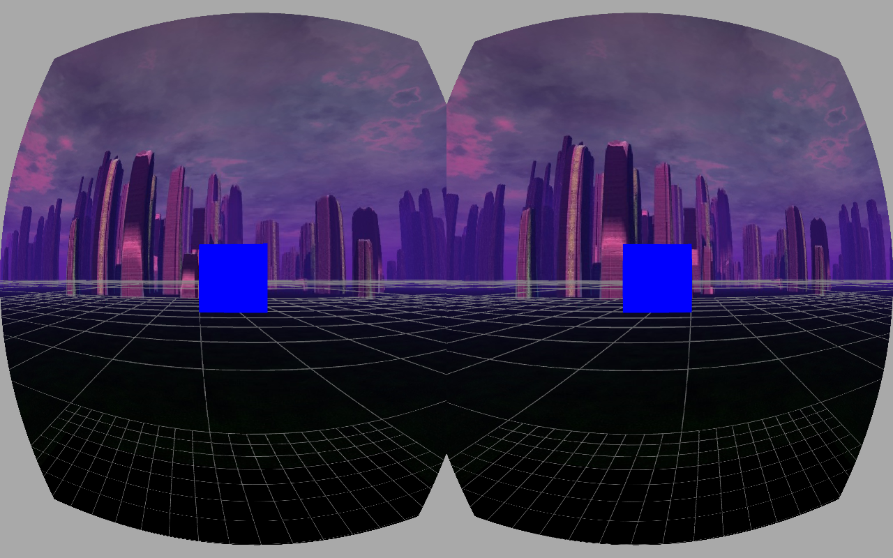
Here are two images that have correctly set up projection and modelview matrices.
 |
 |
| Correct matrices centered view |
Correct matrices view shifted to the left |
Notice that in the left image, the left eye view of the cube has it's left side lined up almost perfectly with the center-line of the floor, which stretches straight away from the viewer into the horizon. The right eye view of the left image has the cube's right face similarly lined up.
The floor line is over a meter distant, and is far less affected by parallax, while the cube is very close to the face and very small, so it's affected more. The right image has the viewpoint shifted slightly to the left, so the left side of the cube has come into view, but only for the left eye. The right eye is still seeing only the front face of the cube.
When running this application, when you get to the part of the code for rendering each eye, the projection matrix and modelview matrix are both already set to values specific to the overall field of view and aspect ratio (for the projection matrix) and the camera position (for the modelview matrix). For each eye I must apply a per-eye specific projection offset (which is a horizontal translation matrix) as well as a modelview offset (another horizontal translation matrix).
Let's take a look at what it means to get the modelview matrix wrong first.
Messing with the modelview matrix
The modelview matrix is used to set the initial position of the virtual camera in the world (the 'view' portion of the matrix) after which the transformations of items in the scene (the 'model' portions of the matrix) are applied and removed in turn as we render them. For stereoscopic rendering you need to take the basic view matrix and modify it slightly for each eye, so that you reproduce the way eyes view the world from different positions.The actual value of the modelview offset is a translation on the X axis of half the value of the IPD, either in the positive direction or the negative direction, depending on the eye. This makes sense because it means that the two matrices together represent a total distance of exactly the IPD value, or more prosaically, the distance between your eyes. The left eye's translation is in the positive X direction (to the right) and the right eye's is in the negative direction (to the left). This is because by applying them to the modelview matrix you're essentially shifting the world in that direction, which is the same as moving the camera in the opposite direction.
Missing modelview offset matrix
If you fail to apply the per-eye modelview offset, you'll cease to render stereoscopic images and simply be rendering a very wide view of a 2D scene. Kind of like if you went to see a 3D movie and took two pairs of 3D glasses and watched with the left lens from each set over your eyes.If in our application we fail to apply the modelview matrix offset for each eye, we get these images:
 |
 |
| Missing modelview centered view |
Missing modelview view shifted to the left |
If the viewpoint is again moved to the left then the new image again has a possible interpretation as a large cube very far away. However, if you're looking through the Rift as the movement occurs, then the cube moves relative to the ground. Your brain can interpret this in any number of ways, from assuming that the cube is moving in the opposite direction you do whenever you move, to making you think you're hallucinating and triggering motion sickness.
The telltale sign that you're not applying the modelview matrix is the lack of parallax. The left or right side of the cube always comes into view in both eyes at the same time, and always shows the same area of the side to each eye.
Inverted modelview offset matrix
If you don't render items very close to the viewer, it's not always easy to tell that you're missing the per-eye modelview offset. In fact it's possible to invert the modelview offset and still not have it apparent.With our handy test cube, it's very apparent:
 |
| Inverted modelview matrix view shifted to the left |
Applying an inverted matrix is surprisingly easy to do. Because the per-eye modelview offset matrices are simple translations, each eye's offset matrix is actually the inverse of the other eye's offset matrix. What's more, depending on how you're developing you might be applying the offset to a 'camera' or 'player' matrix instead of the modelview matrix. The value of the modelview matrix is the inverse of the camera matrix, so if you want to apply the offsets to the camera before using it to create a modelview matrix, then you're supposed to use the inverse of the offset you would use on the modelview matrix. So in this case you'd be applying a negative X translation to the left camera (move the left eye perspective to the left) and so on.
If you really want to get into hair pulling territory, consider that if you both apply the offset matrix to the wrong eye and to the wrong starting point (say, applying it to the camera instead of to the modelview matrix) the two errors cancel each other out, but if you discover one of them and fix it, you've suddenly broken your application.
Incorrectly order of operations on the modelview matrix
There's another way to break the modelview matrix, even if you're using the correct values, and that's doing the incorrect order of operations. Matrices are not commutative. If you have matrix A and matrix B andyou multiply them together, the result you get depends on the order in which you multiply them.
In other words: (A*B) != (B*A)
When you apply the per-eye modelview offset O to the modelview matrix MV, you basically have a choice as to whether you want the operation to be MV=O*MV, known as pre-multiplication or MV=MV*O, known as post-multiplication. The difference ends up being the coordinate system that gets used when you apply the translation.
Spoiler: the correct way to do it is pre-multiplication.
If you perform pre-multiplication you're basically saying that you want the translation to come first, and then to apply all the other transformations stored in the modelview matrix. This forces the effect offset to be carried along through all the other operations, meaning that in the end, the offset is still there, but it's relative to wherever the camera would have been without it. So the offset ends up being relative to whatever direction the camera is pointing.
If you perform post-multiplication, then you're adding the transformation last after all the other changes. This means that the offset is in world coordinates.
Here are two images with the modelview offset applied using post-multiplication:
 |
 |
| Post-multiplied modelview centered view |
Post-multiplied modelview view rotated around to the left |
The left image actually looks perfectly fine. To understand why, you have to realize that if you're looking down the Z axis, with negative X to the left and positive X to the right, then the camera coordinate system lines up with the world coordinate system. As long as that's the case, everything looks correct. However, as soon as you start to move around, say by 'strafing' the cube a little bit so you can see it from the left side, weird things start to happen.
In the right image, the right eye cube appears significantly larger than the left eye cube. That's because the viewpoints are still being offset along the world X axis, even though my eyes are no longer aligned with that axis. Because I'm now almost looking directly down the X axis, my right eye is effectively shifted forward a few centimeters, an my left eye is shifted backwards. They're no longer as far apart left to right as they were before.
Again, if there are no nearby objects in the scene to test this with then it's possible to miss it entirely. The near/far effect is fairly obvious on a cube less than half a meter from your face, but if something is 4 meters away, detecting that it's 3 cm closer or 3cm further away in one eye versus the other can be hard to do. On the other hand the effect might still trigger motion sickness without making it obvious what the problem is.
Messing with the projection matrices
Thankfully, messing up the projection matrix is usually a little less subtle. Here are a couple of image that have the correct modelview matrix, but haven't applied the projection matrix.
|

|
| Missing projection offset centered view |
Missing projection offset view shifted to the left |
 |
| Another way of getting double-vision ... don't sweat it if this gag goes completely over your head |
So what about pre-vs-post multiplication? The offset that's applied to the projection matrix has the effect of basically rotating the view frustum. That's pretty non-intuitive since the offset is a simple translation, but that's the way it is. It's also probably not a mathematically correct description of what's happening, but honestly, matrices are not my big thing.
Regardless, by applying the offset correctly you're changing the spot in the viewport that represents what's directly ahead of the viewer, and consequently changing the portion of the viewport that represents what's to the left of ahead and what's to the right. This is useful because it puts the 'center' of the scene under the lens axis, and it mimics real vision, by giving a greater amount of the overall per-eye FOV to the outer edge of the vision. You can see more to your left from your left eye than your right, etc.
Applying a post-multiplication also 'sort of' rotates the view frustum, but it seems to do so by moving the near clipping plane. You can see the effect in the following image:
 |
| Post-multiplied projection offset |
These projection matrices allow you to see two opposing sides of the cube, which is incorrect. I haven't really tried this on larger scene with more distant objects. This effect is also likely to make it difficult to fuse the images, and it seems like it would be hard to miss the issue, but it might also not be immediately obvious what the problem is. Fortunately, you've read my blog post, so you're using the magic color cube trick to diagnose the problem and realize what's gone wrong.
Congrats, you've gotten to the end of this post. Please join me for my next post: "Why Brian Michael Bendis' treatment of Wanda Maximoff is total bullshit". Again, don't be upset if that joke is meaningless to you.
BRILLIANT article, I've been looking for something like this to make sure I get the Projection matrix transformation perfect for my hobby Oculus engine. Thanks so much.
ReplyDeleteThank you, you're very kind.
ReplyDeleteThe projection matrix takes a different horizontal translation that provides the correct per-eye field of view and also serves to center.
ReplyDelete