For demos that I work on, there are three simple things that I always do to create a better user experience:
make sure the Oculus health and safety warning (HSW) has been dismissed before any other information is displayed
give the user the option to re-center their avatar after they’ve put the headset on and settled in a comfortable position
encourage the user to create a profile
If you are a regular reader of this blog, you know this isn't the first time I've covered thesetopics. However, now that Unity includes native VR support I wanted to revisit these tips and show how to do them with Unity 5.2.1, the 0.7 runtime, and the Oculus Utilities for Unity 0.1-beta package.
Knowing when the HSW has been dismissed
The HSW is a big rectangle centered in front of the user. While it is semi-transparent, it blocks the user’s view significantly. For that reason, I like to make sure that is has been dismissed before displaying anything the user needs to interact with.
The Oculus Utilities for Unity 0.1-beta package provides a way to check to see if the HSW is still displayed:
OVRManager.isHSWDisplayed
This returns true when the HSW is displayed and false when it is not. Note that if you are running the application in the Editor, you won't see the HSW in the Editor window, however, the HSW will appear in the Rift view.
Re-centering the avatar
It is helpful to give users the option to re-center their virtual selves and this is one of the functions available as part of the Unity native VR implementation.
To re-center, add the VR name space and use:
VR.InputTracking.Recenter()
Encouraging the user to create a profile
If the user has not created a profile, the user may experience discomfort because the default IPD or height is different from their own. In previous versions, you could get the name of the profile in use, and if the name returned was "default," you would know that the user had not created a profile. Unfortunately, I’m not seeing a way to do that with the Oculus Utilities for Unity 0.1-beta package. I tried using OVRManager.profile.username, but itreturns "Oculus User" and not the name from the user profile. Looking at OVRProfile, it appears that only ipd, eyeHeight, and eyeDepth are retrieved from the current user profile (Note: you can get the user's eye height and IPD using OVRManager.profile.eyeHeight and OVRManager.profile.ipd.)
For now, I’ll just stress the importance of creating a profile in the documentation. If anyone knows how to get the current user name, please comment!
The first video game influenced dream I remember having was back in the late eighties. I was obsessed with Tetris and had very vivid dreams of Tetris blocks falling on me. So, it isn’t surprising to me that playing video games can change the way you dream. That said, the specific effect that working with the Rift has had on my dreams did surprise me.
When using the Rift, you are sitting in place and the the world moves around or past you instead of like real-life where you move though the world. I find now in my dreams, no matter what I am dreaming about, there are now two kinds of movement - movement where I dream I am moving through a world and movement where I am still and the world moves around or past me. Perhaps, this kind of dreaming is an attempt by my brain to make Rift movement feel more natural to me? Anyone else dreaming like this?
A common interaction in real life is to raise your hand to get someone’s attention. We do it when we are meeting someone in a crowd to help them find us, we do it when we are at school to get the teacher’s attention, and we do it as parents to get our child’s attention so they know that we are there and watching. We also do it when we want to hail a cab or make a bid at an auction. It is a simple enough interaction that babies do it almost instinctively. As simple as raising your hand is, using it as a mechanic in a VR environment brings up some interesting questions. How high should the user raise their hand to trigger the interaction? How long does the user need to have their hand raised? And, what should happen if the application loses hand tracking?
To experiment with this interaction, I created a demo consisting of a single character idling, minding his own business. When the user raises their hand, the character waves back and a speech bubble appears saying “Hello, there!”
Let’s take a look at the demo setup and then look at how testing the user experience went.
For the character animation, I used the Idle and Wave animations from the Raw Mocap data package for Macanim by Unity Technologies (free animations created from motion capture data) and I created an animation controller for the character to control when he is idling and when he waves back at you. The animation controller has two animation states, Idle and Wave. It also has two triggers that can be used to trigger the transition between each state:
The animation controller for the waving character has two states and two triggers.
And, of course, I wrote a script (wavinghello.cs) to detect when the user has raised their hand. The interesting bit of this script is how you know where the user’s hands are and how you know when a hand has been raised high enough so that you can trigger the appropriate animation. Let's take a look at the script's Update() function:
To get the all of the hands in the scene, the script uses GetAllPhysicsHands()
from HandController.cs:
HandModel[] userHands = handController.GetAllPhysicsHands(); GetAllPhysicsHands() returns an array of all Leap physics HandModels for the specified HandController. To get each hand's position, the script uses GetPalmPosition() which returns the Vector3 position of the HandModel relative to the HandController. The HandController is located at 0, 0, 0 relative to its parent object, the CenterEyeAnchor.
The HandController is a child of the CenterEyeAnchor.
The HandController is located at 0, 0, 0 relative to its parent the CenterEyeAnchor.
The CenterEyeAnchor object is used by the Oculus Rift integration scripts to maintain a position directly between the two eye cameras. As the cameras are the user’s eyes, if the Y value of a HandModel object's position is greater than the Y value of the centerEyeAnchor, we know the user's hand has been raised above eye level.
The user experience
When testing this demo I was looking at how high the user should raise their hand to trigger the interaction, how long the user should have their hand raised, and, what the application should do when it loses hand tracking. Initially, I went with what seemed comfortable for me. I required the users to raise their hand (measured from the center of their palm) to above eye level and I did not require the user's hand to be raised for any specific amount of time. If the Leap lost hand tracking, the application treated it as though all hands were below eye level.
I then grabbed three people to do some testing. The only instruction I gave them was to “raise your hand to get the guy’s attention.” For my first user, the demo worked quite well. He raised his hand and the character waved back as expected. Great so far. My second user was resistant to raising his hand any higher than his nose. He quickly got frustrated as he could not get the guy’s attention. My third user raised his hand and then waved it wildly around so much so that the speech bubble flickered and was unreadable. Quite a range of results for only three users.
For my next iteration, I set the threshold for raising one’s hand a few centimeters below eye level.
models.GetPalmPosition().y >= centerEyeAnchor.transform.position.y - 0.03f
This worked for my second user as it was low enough that he would trigger the interaction, but not so low that he would accidentally trigger it.
I haven’t done anything to address the third user yet, but whatever I do, waving my hands like a maniac is now part of my my own testing checklist.
I’d love to hear if anyone else is using this type of mechanic and what their experiences are.
I downloaded Unity 5 yesterday and gave it a quick trial run with the Oculus Integration Package 0.4.4 for the DK2. To test it out, I first built a quick sample scene using assets found in the Unity standard asset packages. Using that scene, I then tried two methods for getting the scene onto the Rift:
Using the OVRPlayerController prefab
Using the First Person Controller prefabs and scripts found in the Unity Standard Assets with the OVRCameraRig prefab
Here’s how those experiments went.
Creating the sample scene
I created a similar sample scene to the one I’ve been using for previoustests - a beach scene using only Unity standard assets. Unity 5 includes a significant refresh of the standard asset packages which is very cool. And nicely for me, they still include palm trees and a sand texture. One change of note is that skyboxes are now set in Window ->Lighting instead of Edit -> Render Settings. Unity 5 comes with a single default skybox which is what I used in this scene. Unity 5 doesn’t include a skyboxes standard asset package, at least not that I found. I did try using the SunnySky box material from the skyboxes package in 4.6 but it does not render nicely.
After downloading and importing the Unity 4 Integration Package 0.4.4, the first thing I tried was just dropping the OVRPlayerController prefab into the scene. The OVRPlayerController character height is 2, so when placing the prefab in the scene I made sure to set the Y value to 1 so it was not colliding with the beach plane. And unlike 4.6, the palm tree assets have colliders attached, so I also made sure my player was placed so that it was not colliding with a palm tree.*
However, before I could build the scene, I needed to address the two errors I was getting:
Assets/OVR/Scripts/Util/OVRMainMenu.cs(250,43): error CS0117: `UnityEngine.RenderMode' does not contain a definition for `World' Assets/OVR/Scripts/Util/OVRMainMenu.cs(969,43): error CS0117: `UnityEngine.RenderMode' does not contain a definition for `World'
To get the scene to build, I edited OVRMainMenu.cs and changed:
c.renderMode = RenderMode.World;
to
c.renderMode = RenderMode.WorldSpace;
in the two places where that line occurs. With that done, I was a able to build and run the scene on the DK 2.
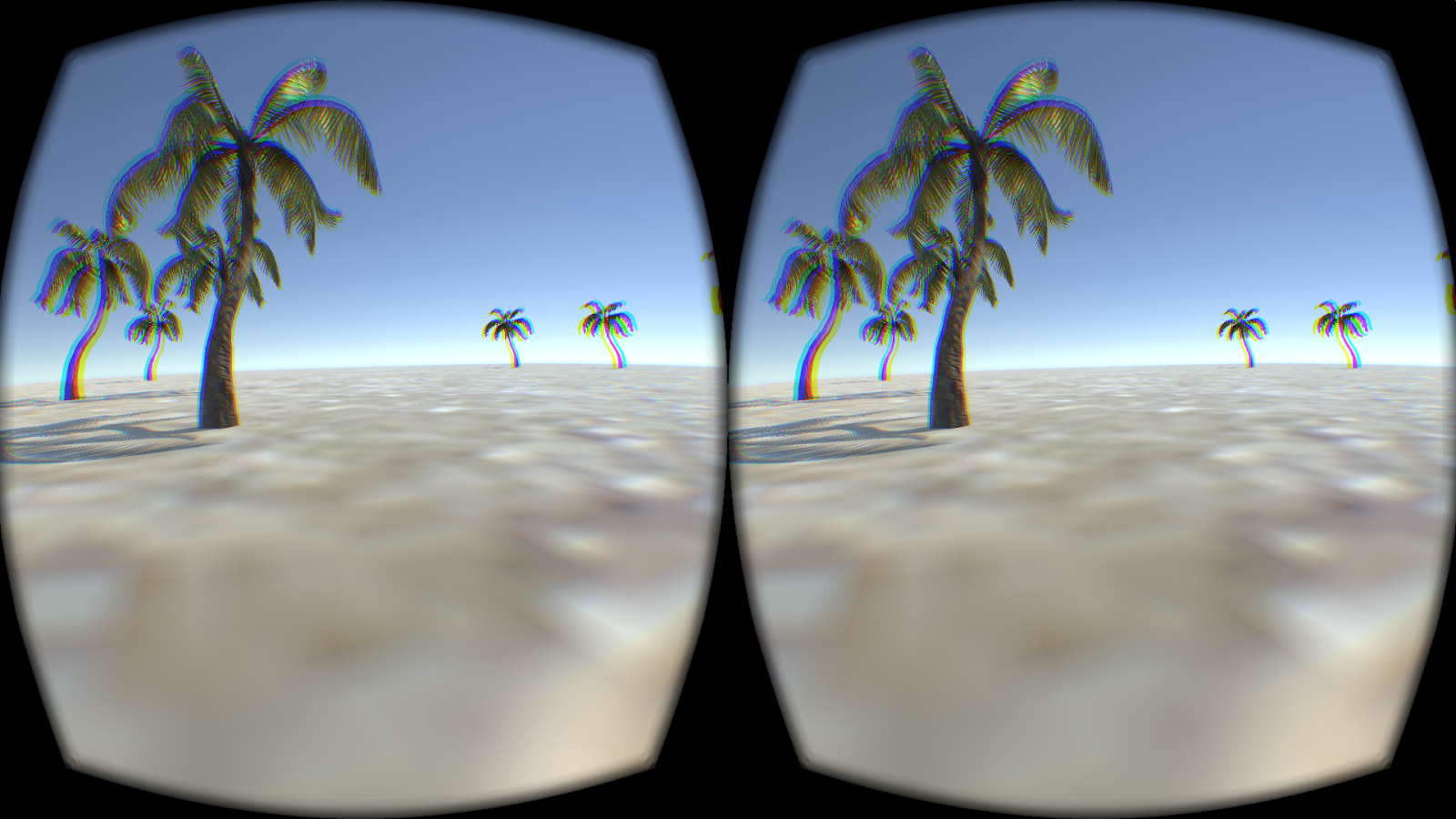
Beach scene on the Rift
Running this on a MacBook Pro in mirrored mode I was seeing 60 or so FPS, and in extended mode around 75.
*Actually, I didn’t make sure of that on the first test and at the start of the scene the collision caused the scene to jitter around and it was very unpleasant.
Using the OVRCameraRig with the first person character controller prefabs from the standard assets
My next test was to try to use the OVRCameraRig prefab with the first person character controller from the standard assets. This did not go as well. With 5.0, there are two First Person Player prefabs: FPSController and RigidbodyFPSController.
The FPSController prefab
The FPSController prefab uses the FirstPersonController.cs script. This script has a number of options, including footstep sounds, head bob and FOV Kick. These options can be great in traditional games but for VR, they can be rather problematic. Head bob and FOV Kick are particularly concerning as these types of motion can be severe motion sickness triggers for some user. Based on that, I didn’t want to spend too much time trying to adapt this script. Instead, I looked at the RigidBodyFPSController.
RigidBodyFPSController
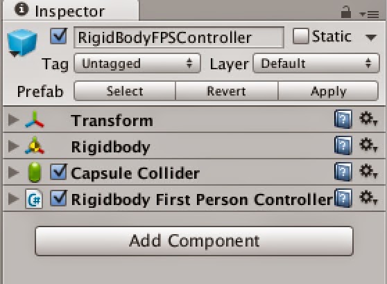
The RigidBodyFPSController prefab consists of the RigidBodyFPSController object with the MainCamera as a child object.
Looking a the RigidBodyFPSController object, you can see that it has a RigidBody, a Capsule Collider and the Rigidbody first person controller script.
To adapt this prefab for use in VR, I first deleted the MainCamera child object and then added the OVRCameraRig in its place.
Note: The MainCamera had a headbob.cs script attached to it. Head bob isn’t something I want in my VR application, and the documentation says that script can be safely disabled or removed.
The Rigidbody First Person Controller script’s Cam variable had been set to the MainCamera. With the MainCamera removed, in the inspector for the script I set it to LeftEyeAnchor.
I then gave the it a test run.
I was seeing similar FPS as in the OVRPlayerController test but the scene was noticeably more jittery. This may be due to using LeftEyeAnchor as the camera but it would require more research to know what is really going on.
Update: March 30, 2015
The build errors appear to be fixed in the 0.5.0.1 Beta version of the Integration Package. When using 0.5.0.1 you need make sure you have updated to the 0.5.0.1 Beta version of the Runtime Package for it to work. I was not able to build my project until I had updated the Runtime Package as well.
One of the demos that I have really enjoyed is the “Trial of the Rift Drifter” by Aldin Dynamics. In this demo you answer questions by shaking your head for yes and no. This is a great use of the head tracker data beyond changing the user’s point of view. And it is a mechanic that I would like to add to my own applications as it really adds to the immersive feel.
As an example, I updated the thought bubbles scene I created earlier to allow a silent conversation with one of the people in the scene and this blog post will cover exactly what I did.
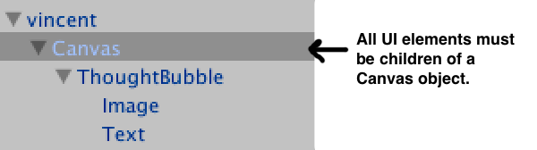
In my scene, I used a world-space canvas to create the thought bubble. This canvas contains a canvas group (ThoughtBubble) which contains an image UI object and a text UI object.
Hierarchy of the world space canvas
I wanted the text in this canvas to change in response to the user shaking their head yes or no. I looked at a couple of different ways of detecting nods and head shakes, but ultimately went with a solution based on this project by Katsuomi Kobayashi.
To use the gesture recognition solution from this project in my own project, I first added the two Rift Gesture files (RiftGesture.csand MyMath.cs) to my project and then attached the RiftGesture.cs script to the ThoughtBubble.
When you look at RiftGesture.cs, there are two things to take note of. First, you’ll see that to get the head orientation data, it uses:
OVRPose pose = OVRManager.display.GetHeadPose(); Quaternion q = pose.orientation;
This gets the head pose data from the Rift independent of any other input. When I first looked at adding head gestures, I tried using the transform from one of the cameras on the logic that the camera transform follows the head pose. Using the camera transform turned out to be problematic because the transform can also be affected by input from devices other than the head set (keyboard, mouse, gamepad) resulting in detecting a headshake when the user rotated the avatar using the mouse rather than shaking their head. By using OVRManager.display.GetHeadPose(), it ensures you are only evaluating data from the headset itself.
Second, you will also notice that it uses SendMessage in DetectNod() when a nod has been detected:
SendMessage("TriggerYes", SendMessageOptions.DontRequireReceiver);
and in DetectHeadshake() when a headshake has been detected:
SendMessage("TriggerNo", SendMessageOptions.DontRequireReceiver);
The next step I took was to create a new script (conversation.cs) to handle the conversation. This script contains a bit of setup to get and update the text in the canvas and to make sure that the dialog is visible to the user before it changes. (The canvas groups visibility is set by canvas groups alpha property.) However, most importantly, this script contains the TriggerYes() and TriggerNo() functions that receive the messages sent from the RiftGesture.cs. These functions simply update the text when a nod or headshake message has been received. I attached the conversation.cs script to the ThoughtBubble object and dragged the text object from the canvas to the questionholder so that the script would know which text to update.
Scripts attached to the ThoughtBubble canvas group
At this point I was able to build and test my scene and have a quick telepathic conversation with one of the characters.
I’m really liking the new GUI system for 4.6. I had been wanting to play a bit with a comic-book style VR environment and with world space canvases, and now is the time.
Here's a quick rundown of how I created the character thought bubbles in this scene using world space canvases.
Creating world space canvases
Canvases are the root object for all Unity GUI elements. By default they render to screen space but you also have the option of rendering the canvas in world space, which is exactly what you need for the Rift. To create a canvas, from the Hierarchy menu, select Create > UI > Canvas. When you create a canvas, both a Canvas object and an Event System object are added to your project. All UI elements need to be added as children of a Canvas. Each thought bubble consist of world-space Canvas, and two UI elements - an image and a text box. For organization, I put the UI elements in an empty gameObject called ThoughtBubble.
Note. Hierarchy order is important as UI objects are rendered in the order that they appear in the hierarchy.
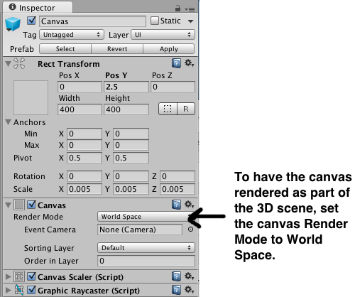
To have the canvas render as part of the 3d scene, in the Inspector for the Canvas, set the Render Mode to World Space.
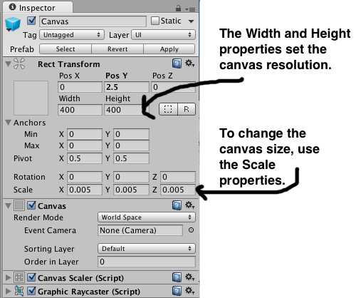
When you change the render mode to world space, you’ll note that the Rect Transform for the canvas becomes editable. Screen space canvases default to the size of the screen, however, for world space canvases you need to set the size manually to something appropriate to the scene.
Setting canvas position, size, and resolution
By default the canvas is huge. If you look in the Inspector, you'll see that it has Width and Height properties as well as Scale properties. The height and width properties are used to control the resolution of the GUI. (In this scene the Width and Height are set to 400 x 400. The thought bubble image is a 200 X 200 px image and the font used for the Text is 24pt Ariel.) To change the size of the canvas you need to set the Scale properties.
To give you an idea of the proportions, the characters in the scene are all just under 2 units high. and the scale of each canvas is set to 0.005 in all directions. With the canvas a reasonable size, I positioned each canvas just above the character.
Rotating the canvas with the player's view
For the thought bubble to be read from any direction, I attached a script to the Canvas to set the canvas transform to look at the player .
When you look at a character the thought bubble appears. The thought bubble remains visible until the you look at another character. There were two ways I looked at for toggling the menu visibility - setting the active state of the UI container gameObject (ThoughtBubble) or adding a Canvas Group component to the UI container gameObject and setting the Canvas Group's alpha property. Changing the alpha property seemed easier as I would not need to keep track of inactive gameObjects, so I went with that method. There is a canvas attached to each character in the scene. The script below is attached to the CenterEyeObject (part of the OVRCameraRig prefab in the Oculus Integration package v. 0.4.4). It uses ray casting to detect which person the user is looking at and then changes the alpha value of the character's attached GUI canvas to toggle the canvas visibility.
Despite some of the bad press it's gotten lately, I quite like OpenGL. However, it has some serious limitations when dealing with the kind of distortion required for VR.
The problem
VR distortion is required because of the lenses in Ouclus Rift style VR headsets. Put (very) simply, the lenses provide a wide field of view even though the screen isn't actually that large, and make it possible to focus on the screen even though it's very close to your eyes.
However, the lenses introduce curvature into the images seen through them. If you render a cube in OpenGL that takes up 40° of your field of view, and look at it through the lenses of the Rift, you'll see curvature in the sides, even though they should be straight.
In order to correct for this, the current approach to correction is to render images to textures, and then apply distortion to the textures. Think of it as painting a scene on a canvas of latex and then stretching the latex onto a curved surface. The curvature of the surface is the exact inverse of the curvature introduced by the lenses, so when you look at the result through the lens, it no longer appears distorted.
However, this approach is extremely wasteful. The required distortion magnifies the center of the image, while shrinking the outer edges. In order to avoid loss of detail at the center, the source texture you're distorting has to have enough pixels so that at the area of maximum magnification, there is a 1:1 ratio of texture pixels to screen pixels. But towards the edges, you're shrinking the image, so all your extra rendered pixels are essentially going to waste. A visual representation of this effect can be seen in my video on dynamic framebuffer scaling below, at about 1:12.
A possible solution...
So how do we render a scene with distortion but without the cost of all those extra pixels that never make it to the screen? What if we could modify the OpenGL pipeline so that it renders only the pixels actually required?
The modern OpenGL pipeline is extremely configurable, allowing clients to write software for performing most parts of it. However, one critical piece of the pipeline remains fixed: the rasterizer. During rendering, the rasterizer is responsible for taking groups of normalized devices coordinates (where the screen is represented as a square with X and Y axes going from -1 to 1) representing a triangle and converting them to lists of pixels which need to be rendered by the fragment shaders. This is still a fixed function because it's the equivalent of picking 3 points on a piece of graph paper and deciding which boxes are inside the triangle. It's super easy to implement in hardware, and prior to now there hasn't been a compelling reason to mess with it.
But just as the advent of more complex lighting and surface coloring models made the fixed function vertex and fragment shaders in the old pipeline led to the rise the current model, the needs of VR give us a reason to add programmability to the rasterizer.
What we need is a way to take the rasterizers traditional output (a set of pixel coordinates) and displace them based on the required distortion.
What would such a shader look like? Well, first lets assume that the rasterizer operates in two separate steps. The first takes the normalized devices coordinates (which are all in the range [-1,1] on both axes) and outputs a set of N values that are still in normalized devices coordinates. The second step displaces the output of the first step based on the distortion function.
In GLSL terms, the first step takes three vec3 values (representing a triangle) and outputs N vec3 coordinates. How many N depends on how much of the screen the triangle covers and also the specific resolution of the rasterization operation. This would not be the same resolution as the screen for the same reason that we render to a larger than screen resolution texture in the current distortion method. This component would remain in the fixed function pipeline. It's basically the same as the graph paper example, but with a specific coordinate system.
The second step would be programmable. It would consist of a shader with a single vec2 input and a single vec2 output, and would be run for every output of the first step (the vec3's become vec2's because at this point in the pipeline we aren't interacting with depth, so we only needs the xy values of the previous step).
in vec2 sourceCoordinate;
out vec2 distortedCoordinate;
void main() {
// Use the distortion function (or a pre-baked structure) to
// compute the output coordinate based on
// the input coordinate
}
Essentially this is just a shader that says "If you were going to put this pixel on the screen here, you should instead put it here". This gives the client the displace the pixels that make up the triangle in exactly the same way they would be displaced using the texture distortion method currently used, but without the cost of running so many extra pixels through the pipeline.
Once OpenGL has all the output coordinates, it can map them to actual screen coordinates. Where more than one result maps to a single screen coordinate, OpenGL can blend the source pixels together based on each's level of contribution, and send the results as a single set of attributes to the fragment shader.
The application of such a rasterization shader would be orthogonal to the vertex/fragment/geometry/tesselation shaders, similar to the way compute shaders are independent. Binding and unbind a raster shader would have no impact on the currently bound vertex/fragment/geometry/tesselation shader, and vice versa.
Chroma correction
Physical displacement of the pixels is only one part of distortion correction. The other portion is correction for chromatic aberration, which this approach doesn't cover.
One approach would be to have the raster shader output three different coordinates, one for each color channel. This isn't appealing because the likely outcome is that the pipeline then has to run the fragment shader multiple times, grabbing only one color channel from each run. Since avoiding running the fragment shader operations more than we have to is the whole point of this exercise, this is unappealing.
Another approach is to add an additional shader to the program that specifically provides the chroma offset for each pixel. In the same way you must have both a vertex and a fragment shader to create a rendering program in OpenGL, a distortion correction shader might require both a raster and a chroma shader. This isn't ideal, because only the green channel would be perfectly computed for the output pixel it covers, while the red and blue pixels would be covering either slightly more or slightly less of the screen than they actually should be. Still it's likely that this imperfection would be well below the level of human perception, so maybe it's a reasonable compromise.
Issues
Cracks
You want to avoid situations where two pixels are adjacent in the raster shader but the outputs have a gap between them when mapped to the screen pixels. Similar to the way we use a higher resolution than the screen for textures now, we would use a higher resolution than the screen for the rasterization step, thus ensuring that at the area of greatest magnification due to distortion, no two two adjacent input pixels cease to be adjacent when mapped to actual physical screen resolution
Merging
An unavoidable consequence of distortion, even without the above resolution increase is that pixels that are adjacent in the raster shader inputs will end up with their outputs mapping to the same pixel.
Cost
Depending on the kind of distortion required for a given lens, the calculations called for in the raster shader might be quite complex, and certainly not the kind of thing you'd want to be doing for every pixel of every triangle. However, that's a fairly easy problem to solve. When binding a distortion program, the OpenGL driver could precompute the distortion for every pixel, as well as precompute the weight for each rasterizer output pixel relative to the physical screen pixel it eventually gets mapped to. This computation would only need to be done once for any given raster shader / raster raster resolution / viewport resolution required. If OpenGL can be told about symmetry even more optimization is possible.
You end up doing a lot more linear interpolation among vertex attributes during the rasterization state, but all this computation is still essentially the same kind of work the existing rasterization stage already does, and far less costly than a complex lighting shader executed for a pixel that never gets displayed.
Next steps
Writing up something less off the cuff
Creating a draft specification for what the actual OpenGL interface would look like
Investigating a software OpenGL implementation like Mesa and seeing how hard it would be to prototype an implementation
Pester nVidia for a debug driver I can experiment with
Learn how to write a shader compiler
Maybe figure out some way to make someone else do all this
Oculus recently released the 0.4 version of the SDK. I am primarily a Mac developer and the fact that it isn’t available for the Mac yet is a big disappointment to me. So while I am impatiently waiting for the Mac version, I’ll poke around the Windows version. As the default profile settings were an irritation to me previously, I checked to see if Oculus made changes to the default profile settings and I am pleased to see that they have:
#define OVR_DEFAULT_GENDER"Unknown"
That’s right. Users who have not yet created a profile are no longer assumed to be “male”. Instead the default matches reality - when the user’s gender is unknown because the user hasn’t specified a gender, the SDK now returns a gender of “Unknown”.
This is a good step as you will no longer get false data from the SDK. Let's take a closer look at the profile default values
// Default measurements empirically determined at Oculus to make us happy
// The neck model numbers were derived as an average of the male and female averages from ANSUR-88
It is also good to see that the "neck model numbers were derived as an average of the male and female averages." However, the height here remains as it has in past SDK versions at 1.778f - the average height of an adult male in the US. I'm a little wary of this value as Oculus doesn't indicate how varied the user pool used to determine this value was. They simply say "a small user study." Was this a varied user pool comprised equally of men and women? How varied were the heights of those in the user pool? Without that information or further study, I can't be sure that these values don't introduce bias and it is something I will keep track of in my own user tests.
I've been keeping such a close eye on this issue because I feel that what the writer Octavia Butler said about science fiction applies here and now to VR.
"There are no real walls around science fiction. We can build them, but they’re not there naturally." -- Octavia Butler
There are no real walls around VR. Let's do what we can to not build those walls. VR is for everyone.
Everyone who knows I own a Rift wants to try it out. In fact, I can’t count how many demos I’ve given since getting it last October. Aside from being really fun to see that "wow" moment when someone first moves their head, it has also given me some good ideas for VR usability. Unfortunately, with all the demos I did, I wasn't writing anything down. Time to stop screwing around and do some science.
About
These notes include reactions from 26 first time Rift users (14 women, 12 men), ranging in age from 11 to 84.
The demos tried were Tuscany, Don’t Let Go, Meld Media GigantosaurusVR, Chicken Walk, Dino Town, Proton Pulse, TNG Engineering, Enterprise and Fortune Teller (my own work-in-progress). The PS3 controller was used with Tuscany, Chicken Walk, and Enterprise. Keyboard with Don’t Let Go, Tuscany, and TNG Engineering. And, nothing is required for Meld Media GigantosaurusVR and Proton Pulse. Time spent using the Rift was between 5 and 10 minutes per person.
Of the 26:
6 would consider themselves to be gamers.
8 said they get motion sickness easily.
Observations
6 did not look around during the demo until prompted.
14 felt symptoms of motion sickness.
7 of the 8 who had said they get motion sickness easily reported symptoms while using the Rift.
Everyone who used the keyboard during a demo needed help finding the keys more than once.
2 gamepad users had trouble using the gamepad. All others had no issues.
12 commented on having an avatar or lack of avatar (depending on the demo used).
User comments
On motion sickness
“Felt motion sickness when walking along the curved wall [of the Enterprise Bridge] but not elsewhere.”
“Down the stairs was nauseating.”
Turning around was very nauseating”
“Felt motion sick all of a sudden. I thought my body should have hit something going through the door but it didn’t.” [Note: this was a very large/wide man.]
“Looking in one direction while moving in another direction was the most nauseating.”
On having an avatar/ lack of avatar
“I felt comfortable being an orb in space but it was like I was viewing video from a hovercraft. In Don’t Let Go the body was very convincing.”
“I have a shoulder!” Said by a smallish woman. This was after the knives in Don’t Let Go.
“Where are my legs. This is weird!”
"Found my shirt!"
“Very visceral” “That is some messed up stuff”[said regards to the spider]
“I have no body! This is so funny!"
“Cool! I can see myself!
On what they loved
“I love the butterflies!” (3)
“Oh, are those birds? How cool!”
“I felt totally immersed.”
Other
“I didn’t think to look around when looking at a screen.”
“I wish I could look at things closely.”
"Felt like I wanted to reach out and touch things”
“The only way to play is in a swivel chair.”
Note:This post was updated on June 23, 2014 to include the reactions of 6 additional test users. This will be the last of the test results for the DK 1.
Right now I'm working on the book, pretty much all the time I'm not working on my day job.
But I'm still hoping to work on a number of other projects involving VR, once I have the time.
Each project is scored 1-10 on difficulty and scope, 10 being hardest / biggest. Each project also has a low medium or high priority to indicate how likely I am to work on it given any amount of time to do so.
So, yesterday the entire world blew up, apparently. My initial reaction was something along the lines of most people's and I think it went something like this
April 1st isn't for a few days yet
'Facebook'... really? But why?
Well, lets go see how the community is reacting to it and... OH MY GOD!
But you know what? I've come to terms with it, and on the whole I believe this is a good thing. I think that the concerns, complaints and observations people have been making deserve addressing.
Working with the Rift requires per-eye manipulation of both the modelview and projection matrix. The modelview matrix needs a horizontal translation that gives objects a sense of depth by providing a different viewpoint for each eye. The projection matrix takes a different horizontal translation that provides the correct per-eye field of view and also serves to center the the scene under the lens axis, instead of in the viewpoint center.
Matrix manipulation can be a bit of a pain, though and getting the manipulation wrong is pretty easy to do. For this reason my initial examples working with the Rift in any language or toolkit always involve rendering a small colored cube of a specific size very close to the viewer. This type of scene serves as a useful test for a variety of ways it's possible to screw up the matrices or their application to the scene.
I'm going to look at why that is, and what the effects of incorrect matrix manipulation look like
User Pogo on the Oculus VR forums asked the other day about why some applications didn't cover more of the available screen real estate on the Rift, and consequently occupied a smaller field of view than was possible.
Every pixel on the Rift display has a fixed relationship with the lenses (discounting the slight differences between the three sets of lenses that come with the Rift). Each pixel has a specific θ (pronounced theta) which represents the angle between the lens axis and the line from the pixel through your eye. Each pixel also has a specific 'perceived θ', which is the perceived angle between the lens axis and the where it appears to be because of the lens distortion.
What this means is that if you're drawing on a smaller area of the Rift screen, you're essentially providing a smaller field of view.
As an example of the issue Pogo posted the following images. The first is from the Oculus configuration utility used to test the IPD and height settings a user has entered.
All three applications are using native Rift support, but are rendering different fields of view. But why? Well, there are a number of reasons that this might happen.
The Oculus Rift sensor hardware reports the acceleration and angular velocity as vectors up to 1000 times a second. It also has a magnetometer and temperature sensor. The iFixit teardown of the Rift reports the gyro+accelerometer chip to be a MPU-6000 from Invensense, which also includes the temperature sensor. The same teardown reports that magentometer is believed to be an A983 2206 chip, which they highlight PCB. All of this hardware is accessed ultimately through the HID interface we discussed in our last post.
Inside the SDK
When tracker data is requested, the SDK opens up the HID device if necessary and configures it with an HID feature report.
Opening the HID device gives you a handle that can be used to read from and write to the device, similar to the kind of handle you'd get from opening a file or a network socket, and typically usable with the same reading and writing APIs.
Feature reports, however, are for reading and writing capabilities and configuration of the device. These do not go over the normal read and write API, but are instead performed 'out-of-band' using an OS specific API. On Linux one uses a special ioctl command. On Win32 based systems it is functions defined by the hid.dll.
The configuration I spoke of consists of issuing a KeepAlive feature report. This instructs the hardware to start sending messages with the acceleration and gyroscope data. If this command isn't issued, reading from the HID device handle will never return any data (and if you're doing blocking reads, will hang the thread). The KeepAlive command includes as a parameter a duration during which it should continue to provide updates. The parameter is stored in a 16 bit value and interpreted as milliseconds, which means that the maximum value is about 65 seconds if it's treated as an unsigned value, or half that if it's treated as signed. The SDK code uses a hard coded of 10 seconds, and is set up to send the keep-alive every 3 seconds, which provides plenty of redundancy in ensuring there are no gaps in the data, even if the background processing thread is somehow held in abeyance for several seconds.
The actual reading of the HID device is done through an asynchronous mechanism that is different for each platform. In an earlier installment we touched on the background thread that handles all SDK commands. The same thread also handles all the reading of data from the HID device handle. When data is available it's copied to a buffer and the buffer is passed to a handler object.
SDK Internal Handler
For once we have a single place to look in the SDK for the implementation. While the code to asynchronously read data and copy it into a buffer is platform specific, the code for interpreting the buffer, a simple array of bytes, is thankfully platform neutral. It is technically located in the SensorDeviceImpl::OnInputReport method, but this is really just a thin wrapper around a non-class function DecodeTrackerMessage located in the same file.
DecodeTrackerMessage converts the incoming data from a byte array into an actual C structure called TrackerSensors, again defined in the same file. This conversion mostly consists of simply copying the bytes to the appropriate location in the structure. The only unusual part of this decoding is that the actual gyroscope and accelerometer vectors are not stored as conventionally sized values. Typically integer values are stored in either 8, 16, 32, or 64 bits, i.e. sizes that are powers of 2. However, for whatever reason, 16 bit values for the individual components of the vectors were deemed insufficiently precise, while 32 bit values were deemed overkill. This makes sense when you look at the units.
Acceleration is typically measured in meters per second squared or in Gs. 1 G is about 9.8 meters per second squared. However, in order to avoid dealing with floating point numbers, this close to the hardware, the numbers are scaled by 1/1000 and reported as integers, so what the hardware is actually reporting is millimeters per second squared. If we were limited to 16 bits, the most acceleration we could represent in any given axis would be about +/- 3 Gs, something that's pretty easy to exceed, particularly on small timescales. On other hand if we use 32 bits we have space for representing about 200,000 Gs. This is starting to approach the surface gravity of a white dwarf star. Perhaps that range has some value in the fields of super-villainy and cartoons, it's certainly more than we need.
...or could possibly survive
The compromise is to use a non-standard bit length. By encoding each axis in 21 bits, we can fit the entire vector into a single 64 bit integer, and still have 1 bit left over. 21 bits allows us to encode about +/- 100 Gs in any direction, which provides plenty of leeway for rapid movements, and probably allows the chip to be used in a variety of more interesting applications that might involve high, though not ludicrous, levels of acceleration.
The input byte array and C structure actually contain room for up to 3 samples, each containing one reading from the accelerometer and one from the gyroscope. It also contains a field for the number of samples that have occurred since the last report. If this number is between 1 and 3, then that is the number of samples in the structure that are valid. If this number is greater than 3 then all three samples are valid and there have been N - 3 samples that have been dropped. The structure only contains 1 magnetic vector and one temperature value, both of which are encoded more conventionally, though still as integers.
Integers to floats
Once the data has been decoded, it needs to be processed by whatever message handler is attached to the sensor device. But dealing with integers of non-SI units could easily be a source of bugs if you get the conversions wrong, plus each tracker message can contain up to 3 samples from the sensors. So the next step is for the sensor device to pass the tracker message to an internal method onTrackerMessage(). This code is responsible for taking the TrackerMessage type, containing ints and up to 3 samples, and converting it into up to 3 individual instances of the MessageBodyFrame class. MessageBodyFrame is a subclass of the basic Message type in the SDK, part of it's generic event handling system. If you connect a callback to the SensorDevice, these are the message you would expect to get from it, at a rate of about 1000 per second. Most people don't do this though, relying instead on a SensorFusion insteance to handle the messages for them and turn them into a continuously available quaternion, representing the current orientation of the Rift.
MessageBodyFrame contains a representation of the acceleration, rotation and magnetic field all as 3 dimensional vectors composed of floating point values, and represented in SI units. Actually the docs say magnetic field is represented in gauss, not teslas, but this isn't really important, because a) the conversion factor is a power of 10, and b) the magnetic field isn't combined with any other units, so it might as well be a unit-less vector. Indeed, the magnetic calibration utility could potentially apply a scaling value to the value, so that it's set up to be a unit vector at all times, but it doesn't appear that it does this currently.
Well, that's all we have time for today. More detailed inner workings of the SDK that you don't care about coming soon to a blog near you.