Friday, December 12, 2014

Unity 4.6: Thought bubbles in a Rift scene using world space canvases

I’m really liking the new GUI system for 4.6. I had been wanting to play a bit with a comic-book style VR environment and with world space canvases,  and now is the time.


Here's a quick rundown of how I created the character thought bubbles in this scene using world space canvases.

Creating world space canvases

Canvases are the root object for all Unity GUI elements. By default they render to screen space but you also have the option of rendering the canvas in world space, which is exactly what you need for the Rift. To create a canvas, from the Hierarchy menu, select Create > UI > Canvas. When you create a canvas, both a Canvas object and an Event System object are added to your project. All UI elements need to be added as children of a Canvas. Each thought bubble consist of world-space Canvas, and two UI elements - an image and a text box. For organization, I put the UI elements in an empty gameObject called ThoughtBubble.


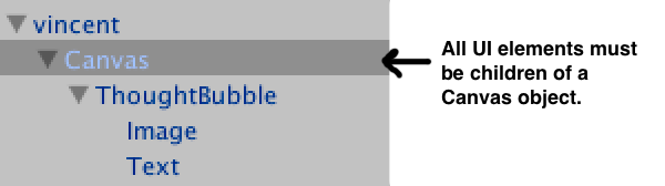
Note. Hierarchy order is important as UI objects are rendered in the order that they appear in the hierarchy.

To have the canvas render as part of the 3d scene, in the Inspector for the Canvas, set the Render Mode to World Space.


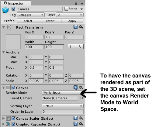
When you change the render mode to world space, you’ll note that the Rect Transform for the canvas becomes editable. Screen space canvases default to the size of the screen, however, for world space canvases you need to set the size manually to something appropriate to the scene.

Setting canvas position, size, and resolution

By default the canvas is huge. If you look in the Inspector, you'll see that it has Width and Height properties as well as Scale properties.  The height and width properties are used to control the resolution of the GUI.  (In this scene the Width and Height are set to 400 x 400. The thought bubble image is a 200 X 200 px image and the font used for the Text is 24pt Ariel.)  To change the size of the canvas you need to set the Scale properties. 


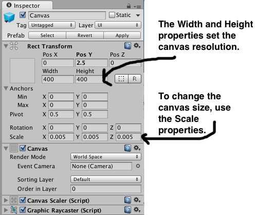
To give you an idea of the proportions, the characters in the scene are all just under 2 units high. and the scale of each canvas is set to 0.005 in all directions.  With the canvas a reasonable size, I positioned each canvas just above the character.

Rotating the canvas with the player's view

For the thought bubble to be read from any direction, I attached a script to the Canvas to set the canvas transform to look at the player .

using UnityEngine;
using System.Collections;

public class lookatplayer : MonoBehaviour {
    public Transform target;
    void Update() {
        transform.LookAt(target);
    }
}


Toggling canvas visibility

When you look at a character the thought bubble appears. The thought bubble remains visible until the you look at another character. There were two ways I looked at for toggling the menu visibility - setting the active state of the UI container gameObject (ThoughtBubble) or adding a Canvas Group component to the UI container gameObject and setting the Canvas Group's alpha property. Changing the alpha property seemed easier as I would not need to keep track of inactive gameObjects, so I went with that method.   There is a canvas attached to each character in the scene. The script below is attached to the CenterEyeObject (part of the OVRCameraRig prefab in the Oculus Integration package v. 0.4.4). It uses ray casting to detect which person the user is looking at and then changes the alpha value of the character's attached GUI canvas to toggle the canvas visibility.

using UnityEngine;
using System.Collections;

public class lookatthoughts : MonoBehaviour {
    
    private  GameObject displayedObject = null;
    private  GameObject lookedatObject  = null;


    // Use raycasting to see if a person is being looked 
    // at and if sodisplay the person's attached gui canvas
    void Update () {
        Ray ray = new Ray(transform.positiontransform.forward);
        RaycastHit hit;

        if(Physics.Raycast(rayout hit100)) {
            if (hit.collider.gameObject.tag == "person"){
                lookedatObject = hit.collider.gameObject;
                if (displayedObject == null){
                    displayedObject = lookedatObject;
                    changeMenuDisplay(displayedObject1);
                }else if (displayedObject == lookedatObject){
                    //do nothing
                }else{
                    changeMenuDisplay(displayedObject0);
                    displayedObject = lookedatObject;
                    changeMenuDisplay(displayedObject1);
                }
            }
        } 
    }

    // Toggle the menu display by setting the alpha value 
    // of the canvas group
    void changeMenuDisplay(GameObject menufloat alphavalue){

        Transform tempcanvas = FindTransform(menu.transform"ThoughtBubble");

        if (tempcanvas != null){
            CanvasGroup[] cg;
            cg = tempcanvas.gameObject.GetComponents<CanvasGroup>();
            if (cg != null){
                foreach (CanvasGroup cgs in cg) {
                    cgs.alpha = alphavalue;
                }
            }
        }
    }
    

    // Find a child transform by name
    public static Transform FindTransform(Transform parentstring name)
    {
        if (parent.name.Equals(name)) return parent;
        foreach (Transform child in parent)
        {
            Transform result = FindTransform(childname);
            if (result != nullreturn result;
        }
        return null;
    }
    
}

Wednesday, November 12, 2014

Unity 4: Knowing which user profile is in use

Previous versions of the Unity Integration package did not include a call for getting the user profile name. As of 0.4.3, it is now possible get the the user profile name. To know which profile is being used, you can use GetString()found in the OVRManager.cs script.

public string GetString(string propertyName, string defaultVal = null)

Below is a simple example script (report.cs) that uses this method to print out the name of the current user profile to the console. To use this script,  attach it to an empty game object in a scene that is using the OVRCameraRig or OVRPlayerController prefab. With the Rift connected and powered on, run the scene in the Unity Editor. If default is returned, no user profile has been found.


using UnityEngine;
using System.Collections;
using Ovr;

public class report : MonoBehaviour {
    void Start () {
     Debug.Log (OVRManager.capiHmd.GetString(Hmd.OVR_KEY_USER, "")) 
    }
}


The GetString()method found in the OVRManager.cs script method is used to get the profile values for the current HMD. The OVRManager.cs script gets a reference to the current HMD, capiHmd. The Hmd class, defined in OvrCapi.cs, provides a number of constants that you can use to get user profile information for the current HMD. In this example, I used OVR_KEY_USER to get the profile name. You could also get the user’s height (OVR_KEY_PLAYER_HEIGHT), IPD (OVR_KEY_IPD) or gender (OVR_KEY_GENDER), for example.

Thursday, November 6, 2014

Thoughts on an alternative approach to distortion correction in the OpenGL pipeline

Despite some of the bad press it's gotten lately, I quite like OpenGL.  However, it has some serious limitations when dealing with the kind of distortion required for VR.

The problem

VR distortion is required because of the lenses in Ouclus Rift style VR headsets.  Put (very) simply, the lenses provide a wide field of view even though the screen isn't actually that large, and make it possible to focus on the screen even though it's very close to your eyes.

However, the lenses introduce curvature into the images seen through them.  If you render a cube in OpenGL that takes up 40° of your field of view, and look at it through the lenses of the Rift, you'll see curvature in the sides, even though they should be straight.

In order to correct for this, the current approach to correction is to render images to textures, and then apply distortion to the textures.  Think of it as painting a scene on a canvas of latex and then stretching the latex onto a curved surface.  The curvature of the surface is the exact inverse of the curvature introduced by the lenses, so when you look at the result through the lens, it no longer appears distorted.

However, this approach is extremely wasteful.  The required distortion magnifies the center of the image, while shrinking the outer edges.  In order to avoid loss of detail at the center, the source texture you're distorting has to have enough pixels so that at the area of maximum magnification, there is a 1:1 ratio of texture pixels to screen pixels.  But towards the edges, you're shrinking the image, so all your extra rendered pixels are essentially going to waste.  A visual representation of this effect can be seen in my video on dynamic framebuffer scaling below, at about 1:12.


A possible solution...

So how do we render a scene with distortion but without the cost of all those extra pixels that never make it to the screen?  What if we could modify the OpenGL pipeline so that it renders only the pixels actually required?

The modern OpenGL pipeline is extremely configurable, allowing clients to write software for performing most parts of it.  However, one critical piece of the pipeline remains fixed: the rasterizer.  During rendering, the rasterizer is responsible for taking groups of normalized devices coordinates (where the screen is represented as a square with X and Y axes going from -1 to 1) representing a triangle and converting them to lists of pixels which need to be rendered by the fragment shaders.  This is still a fixed function because it's the equivalent of picking 3 points on a piece of graph paper and deciding which boxes are inside the triangle.  It's super easy to implement in hardware, and prior to now there hasn't been a compelling reason to mess with it.

But just as the advent of more complex lighting and surface coloring models made the fixed function vertex and fragment shaders in the old pipeline led to the rise the current model, the needs of VR give us a reason to add programmability to the rasterizer.  

What we need is a way to take the rasterizers traditional output (a set of pixel coordinates) and displace them based on the required distortion.  

What would such a shader look like?  Well, first lets assume that the rasterizer operates in two separate steps.  The first takes the normalized devices coordinates (which are all in the range [-1,1] on both axes) and outputs a set of N values that are still in normalized devices coordinates.  The second step displaces the output of the first step based on the distortion function.

In GLSL terms, the first step takes three vec3 values (representing a triangle) and outputs N vec3 coordinates.  How many N depends on how much of the screen the triangle covers and also the specific resolution of the rasterization operation.  This would not be the same resolution as the screen for the same reason that we render to a larger than screen resolution texture in the current distortion method.  This component would remain in the fixed function pipeline.  It's basically the same as the graph paper example, but with a specific coordinate system.  

The second step would be programmable.  It would consist of a shader with a single vec2 input and a single vec2 output, and would be run for every output of the first step (the vec3's become vec2's because at this point in the pipeline we aren't interacting with depth, so we only needs the xy values of the previous step).  

in vec2 sourceCoordinate;
out vec2 distortedCoordinate;

void main() {
  // Use the distortion function (or a pre-baked structure) to 
  // compute the output coordinate based on 
  // the input coordinate
}

Essentially this is just a shader that says "If you were going to put this pixel on the screen here, you should instead put it here".  This gives the client the displace the pixels that make up the triangle in exactly the same way they would be displaced using the texture distortion method currently used, but without the cost of running so many extra pixels through the pipeline.  

Once OpenGL has all the output coordinates, it can map them to actual screen coordinates.  Where more than one result maps to a single screen coordinate, OpenGL can blend the source pixels together based on each's level of contribution, and send the results as a single set of attributes to the fragment shader.  

The application of such a rasterization shader would be orthogonal to the vertex/fragment/geometry/tesselation shaders, similar to the way compute shaders are independent.   Binding and unbind a raster shader would have no impact on the currently bound vertex/fragment/geometry/tesselation shader, and vice versa.  

Chroma correction

Physical displacement of the pixels is only one part of distortion correction.  The other portion is correction for chromatic aberration, which this approach doesn't cover.

One approach would be to have the raster shader output three different coordinates, one for each color channel.  This isn't appealing because the likely outcome is that the pipeline then has to run the fragment shader multiple times, grabbing only one color channel from each run.  Since avoiding running the fragment shader operations more than we have to is the whole point of this exercise, this is unappealing.

Another approach is to add an additional shader to the program that specifically provides the chroma offset for each pixel.  In the same way you must have both a vertex and a fragment shader to create a rendering program in OpenGL, a distortion correction shader might require both a raster and a chroma shader.  This isn't ideal, because only the green channel would be perfectly computed for the output pixel it covers, while the red and blue pixels would be covering either slightly more or slightly less of the screen than they actually should be.  Still it's likely that this imperfection would be well below the level of human perception, so maybe it's a reasonable compromise.

Issues

Cracks
You want to avoid situations where two pixels are adjacent in the raster shader but the outputs have a gap between them when mapped to the screen pixels.  Similar to the way we use a higher resolution than the screen for textures now, we would use a higher resolution than the screen for the rasterization step, thus ensuring that at the area of greatest magnification due to distortion, no two two adjacent input pixels cease to be adjacent when mapped to actual physical screen resolution

Merging
An unavoidable consequence of distortion, even without the above resolution increase is that pixels that are adjacent in the raster shader inputs will end up with their outputs mapping to the same pixel.  

Cost 
Depending on the kind of distortion required for a given lens, the calculations called for in the raster shader might be quite complex, and certainly not the kind of thing you'd want to be doing for every pixel of every triangle.  However, that's a fairly easy problem to solve.  When binding a distortion program, the OpenGL driver could precompute the distortion for every pixel, as well as precompute the weight for each rasterizer output pixel relative to the physical screen pixel it eventually gets mapped to.  This computation would only need to be done once for any given raster shader / raster raster resolution / viewport resolution required.  If OpenGL can be told about symmetry even more optimization is possible.  

You end up doing a lot more linear interpolation among vertex attributes during the rasterization state, but all this computation is still essentially the same kind of work the existing rasterization stage already does, and far less costly than a complex lighting shader executed for a pixel that never gets displayed. 

Next steps

  • Writing up something less off the cuff
  • Creating a draft specification for what the actual OpenGL interface would look like
  • Investigating a software OpenGL implementation like Mesa and seeing how hard it would be to prototype an implementation
  • Pester nVidia for a debug driver I can experiment with
  • Learn how to write a shader compiler
  • Maybe figure out some way to make someone else do all this


Wednesday, October 22, 2014

Video: Rendering OpenCV captured images in the Rift

In this video, Brad gives a walkthrough of an application that pulls images from a live Rift-mounted webcam and renders them to the display.


Links for this video:

Tuesday, October 14, 2014

Using the DK 2 on a MacBook Pro

Updated this information elsewhere so updating it here, too. Here is what I did to get the DK 2 running on the MacBook Pro.

I first downloaded the 0.4.1 SDK and Runtime for the Mac. I then plugged in all cables as recommended in the guide that comes with the DK 2. After getting the cables set up, I installed the Runtime and SDK. The README contains this note:

 “Before using your new DK2, it is critical to update the firmware on the headset. This is important to ensure reliable functioning of your DK2. Use the Config Util to install the firmware file supplied in this release (v2.11). This is only relevant to DK2 owners.”

As I had tested the DK2 out on Windows previously, I had already updated my DK2 firmware to 2.11. Just to be sure, I ran OculusConfigUtil and confirmed that my firmware was up-to-date. While I had it open, I went ahead and created a user profile for myself. Creating a profile can help prevent discomfort when using the Rift.
OculusConfigUtil profile screen

On Windows, there is the new Direct HMD Access display mode which can be set by selecting Tools > Rift Display Mode in the OculusConfigUtil menu. At this time, Direct HMD Access mode is not supported on the Mac.

OculusConfigUtil Display modes selection panel
So for the Mac, the next step is to configure the displays. As with earlier releases, you have the choice of using Extended mode and Mirrored mode. Previously, I had not been able to get Extended mode to work and was forced to use mirroring. Oculus recommends against mirroring, so I gave Extended mode another try.

Extended Mode

In the display preference, I set the displays to extended mode. My laptop screen was set as the main display and the Rift was the extended display.  The Unity Integration guide, in the monitor set up section, says “For DK2, the resolution should be Scaled to 1080p, the rotation should be 90°and the refresh rate  should be 75 Hertz,” so those were the settings I used. 

In the OculusConfigUtil I then selected Show Demo Scene and the demo scene appeared correctly on the Rift. Yeah! 

The desk scene demo accessed by selecting the "Show Demo Scene" button in OculusConfigUtil 

I then tried to run the “Oculus World Demo" and it appeared on my main monitor and not the Rift. The mouse cursor also disappeared so there was no way to move the demo window to the extended portion of the desktop. The Unity Integration guide monitor set up section says “Some Unity applications will only run on the main display. In the Arrangement screen, drag the white bar onto the Rift's blue box to make it the main display.” This was the case with the “Oculus World Demo"  and to view it I needed to set the Rift as the main display and then run the demo.  But, doing so wasn’t as simple as it sounds. 

Working with the desktop is not really possible when looking through the Rift, so I needed to first make sure the “Display Preferences Window” and the finder window with the application I wanted to launch were situated such that they were at least partially on the extended portion of the display before I switched to having the  Rift be the main display. 

Desktop window positioning

With these windows in place, in the “Display Preferences Window” I grabbed the white bar that indicates which display is the main display and dragged it so that the Rift was now the main display. 

You need to grab the white bar that indicates which display is the main display and drag it so that the Rift is main display. 

Then with my main screen as the extended display, I double clicked on the “Oculus world demo” to run it. 
OculusWorldDemo

And the demo ran successfully on the Rift.

That process was very cumbersome, so I decided to also take a look at using mirrored mode.

Mirrored Mode

In the display preferences, I set the displays to mirrored. Again, I needed to rotate the display 90 degrees for the display to be the correct orientation.  

I then ran both the “Oculus World Demo” and the demo in the config Utility. In both cases I saw a lot of judder as I moved my head around (very headache inducing). The release notes have this to say on the topic:

“ Scene Judder - The whole view jitters as you look around, producing a strobing  back-and-forth effect. This effect is the result of skipping frames (or Vsync)  on a low-persistence display, it will usually be noticeable on DK2 when frame rate falls below 75 FPS. This is often the result of insufficient GPU performance or attempting to render too complex of a scene. Optimizing the engine or scene content should help.
We expect the situation to improve in this area as we introduce asynchronous timewarp and other optimizations over the next few months. If you experience this on DK2 with multiple monitors attached, please try disabling one monitor to see if the problem goes away.” 

On a suggestion from Brad, I tried setting the display refresh rate to 60 hertz. This significantly reduced the judder; however, there was noticeable screen blur when I moved my head. The good news on the blur was that unlike the judder, it wasn’t an immediate headache trigger for me.

Which mode will I use?

Which mode I will use will really depend on what I am trying to do.  If I am just using the Rift,  I would choose extended mode  as it does offer better performance. In extended mode I was seeing 75 FPS and in mirrored mode with the refresh rate set to 75 hertz I was seeing 46 FPS and with the refresh rate set to 60 I was seeing 60 FPS.

But until Direct HMD Access mode works on the Mac, unless I am testing for performance, I will probably mostly use mirrored mode when developing.  Mirrored mode allows me to see what the person using the Rift is doing and provides a faster work-flow for doing quick iterations.

Wednesday, October 1, 2014

Video: Dynamic Framebuffer Scaling in the Oculus Rift

In this video Brad discusses dynamic framebuffer scaling in the Oculus Rift:

 
 Links from the video:

Friday, September 26, 2014

Unity: Playing a video on a TV screen at the start of a Rift application

Let’s say you wanted to have a TV screen that plays a short welcome video on start up in your scene, such as in this demo I'm working on:


Displaying video on a screen in a scene in Unity Pro is typically done using a Movie Texture. Movie Textures do not play automatically - you need to use a script to tell the video when to play. The Rift, however, presents some challenges that you wouldn’t face when working with a more traditional monitor that make knowing when to start the video a bit tricky.
  1. You can’t assume that the user has the headset on when the application starts. This means you can’t assume that the user can see anything that you are displaying. 
  2.  On start-up all Rift applications display a Health and Safety Warning (HSW). The HSW is big rectangle pinned to the user’s perspective that largely obscures the user’s view of everything else in the scene.
  3. You aren’t in control of the where the user looks (or rather, you shouldn’t be - moving the camera for the user can be a major motion sickness trigger), so you can’t be sure the user is even looking at the part of the scene where the video will be displayed.
In my demo, I addressed the first two issues by making sure the HSW had been dismissed before I started the video. If the user has dismissed the HSW, it will no longer be in the way of their view and it is a good bet that if they dismissed the HSW, they have the headset on and are ready to start the demo. The third issue I addressed by making sure the video is in the user’s field of view before it starts playing.

Making sure the Health and Safety Warning (HSW) has been dismissed

The HSW says “Press any key to dismiss.” My first thought was to use the key press as the trigger for starting the video. Unfortunately this doesn’t quite work. The HSW must be displayed for a minimum amount of time before it can actually be dismissed - 15 seconds the first time it is displayed for a given profile and 6 seconds for subsequent times. The result was that often the key was pressed and the welcome video would start but the HSW had no yet gone away. I also wanted the video to replay if the user reloaded the scene. When the scene is reloaded, the HSW is not displayed, the user does not need to press a key and therefore the video would not start.

Fortunately, Oculus Unity Integration package provides a way to know if the HSW is still being displayed or not.
OVRDevice.HMD.GetHSWDisplayState().Displayed
The above will return true if the HSW is still on screen.

Making sure the video is in the player’s field of view

How you get the user to look at the video will depend a lot on what kind of scene you are using. You can, for example, put a TV in every corner of the room so that no matter which direction the user is looking, a screen is in view. Or, if you have only a single TV screen, you can use audio cues to get the get the user’s attention. (I haven't decided yet how I will get the user's attention in my demo.)

No matter how you get the player to look at where the video is playing, you can check that the video is within the user’s field of view by checking the video’s render state before playing the video using:
renderer.isVisible
The above will return true if the object (in this case, the TV screen) is currently being rendered in the scene.

Thursday, September 25, 2014

Video: Asynchronous timewarp with the Oculus Rift

In this video Brad discusses an example of using asynchronous timewarp in order to maintain a smooth experience in the Rift even if your rendering engine can't maintain the full required framerate at all times.


Links from the video:

Friday, August 22, 2014

Using basic statistical analysis to discover whether or not the Oculus Rift headset is being worn

As we were getting ready for our talk next week at PAX Dev 2014, entitled "Pitfalls & Perils of VR Development: How to Avoid Them", an interesting question came up: how can you tell if the Rift is actually on the user's head, instead of on their desk?  It's a pretty common (and annoying) scenario right now--you double-click to launch a cool new game, and immediately you can hear intro music and cutscene dialog but the Rift's still on a table.  I hate feeling like, ack!, I have to scramble to get the Rift on my face to see the intro.

Valve's SteamVR will help with this a lot, I expect; if I launch a game when I'm already wearing the Rift, there'll be no jarring switch.  But I'm leery--half the Rift demos I download today start by popping up a Unity dialog on my desktop before they switch to fullscreen VR, and that's going to be an even worse experience if I'm using Steam.

So I was mulling over how to figure out programmatically whether or not the Rift is on the user's head.  I figure that we can't just look at the position data from the tracker camera, because "camera can see Rift" isn't a firm indicator of "Rift is being used".  (Maybe the Rift is sitting on my desk, in view of the camera.)  Instead, we need to look at the noise of its position.

I recorded the eye pose at each frame, taking an average of all eye poses recorded every tenth of a second.  At 60FPS that's about six positions per decisecond.  The Rift's positional sensors are pretty freaking sensitive; when the Rift is sitting on my desk, the difference in position from one decisecond to the next from ambient vibration is on the order of a hundredth of a millimeter.  Pick it up, though, and those differences spike.

I plotted the standard deviation of the Rift's position, in a rolling window of ten samples for the past second, versus time:


This is a graph of log(standard deviation(average change in position per decisecond)) over time.  The units on the left are in log scale.  I found that when the Rift was inert on my desk, casual vibration kept log(σ) < -10.5; as I picked it up log(σ) spiked, and then while worn would generally hover between -4.5 and -10.5.  When the Rift was being put on or taken off, log(σ) climbed as high as -2, but only very briefly.

I found that distinguishing between Rift that was being put on or lifted off from a Rift that was being worn normally was pretty hard with this method, but that the distinction between "not in human hands at all" and "in use" was clear.  So this demonstrates a method for programmatically determining whether the Rift is in active use or not.  I hope it's useful.

Sample code was written in Java, and is available on the book's github repo.  (File "HeadMotionStatsDemo.java".)

Advanced uses of Timewarp II - When you're running late

[This is post three of three on Timewarp, a new technology available on the Oculus Rift. This is a draft of work in progress of Chapter 5.7 from our upcoming book, "Oculus Rift in Action", Manning Press. By posting this draft on the blog, we're looking for feedback and comments: is this useful, and is it intelligible?]


5.7.2 When you're running late

Of course, when the flak really starts to fly, odds are that you won’t be rendering frames ahead of the clock—it’s a lot more likely that you’ll be scrambling to catch up.  Sometimes rendering a single frame costs you longer than the number of milliseconds your target framerate allows.  But timewarp can be useful here too.

Say your engine realizes that it’s going to be running late.  Instead of continuing to render the current frame, you can send the previous frame to the Rift and let the Rift apply timewarp to the images generated a dozen milliseconds ago.  (Figure 5.12.)  Sure, they won’t be quite right—but if it buys you enough time to get back on top of your rendering load, it’ll be worth it, and no human eye will catch it when you drop occasionally one frame out of 75.  Far more importantly, the image sent to the Rift will continue to respond to the user’s head motions with absolute fidelity; low latency means responsive software, even with the occasional lost frame.

Remember, timewarp can distort any frame, so long as it’s clear when that frame was originally generated so that the Rift knows how much distortion to apply.

Figure 5.12: If you’re squeezed for rendering time, you can occasionally save a few cycles by dropping a frame and re-rendering the previous frame through timewarp.

The assumption here is that your code is sufficiently instrumented and capable of self-analysis that you do more than just render a frame and hope it was fast enough.  Carefully instrumented timing code isn’t hard to add, especially with some display-bound timing methods as ovrHmd_GetFrameTiming, but it does mean more complexity in the rendering loop.  If you’re using a commercial graphics engine, they may already have the support baked in.  This is the sort of monitoring that any 3D app engine that handles large, complicated, variable-density scenes will hopefully be capable of performing.

Dropping frames with timewarp is an advanced technique, and probably not worth investing engineering resources into early in a project.  This is something that you should only build when your scene has grown so complicated that you anticipate having spikes of rendering time.  But if that’s you, then timewarp will help.

Tuesday, August 19, 2014

Advanced Uses of Timewarp I - When you're running early

[This is post two of three on Timewarp, a new technology available on the Oculus Rift. This is a draft of work in progress of Chapter 5.7 from our upcoming book, "Oculus Rift in Action", Manning Press. By posting this draft on the blog, we're looking for feedback and comments: is this useful, and is it intelligible?]


5.7.1 When you're running early

One obvious use of timewarp is to fit in extra processing, when you know that you can afford it.  The Rift SDK provides access to its timing data through several API functions:
  • ovrHmd_BeginFrame       // Typically used in the render loop
  • ovrHmd_GetFrameTiming   // Typically used for custom timing and optimization
  • ovrHmd_BeginFrameTiming // Typically used when doing client-side distortion
These methods return an instance of the ovrFrameTiming structure, which stores the absolute time values associated with the frame. The Rift uses system time as an absolute time marker, instead of computing a series of differences from one frame to the next, because doing so reduces the gradual build-up of incremental error. These times are stored as doubles, which is a blessing after all the cross-platform confusion over how to count milliseconds.

ovrFrameTiming includes:
  • float DeltaSeconds
    The amount of time that has passed since the previous frame returned its BeginFrameSeconds value; usable for movement scaling. This will be clamped to no more than 0.1 seconds to prevent excessive movement after pauses for loading or initialization.
  • double ThisFrameSeconds Absolute time value of when rendering of this frame began or is expected to begin; generally equal to NextFrameSeconds of the previous frame. Can be used for animation timing.
  • double TimewarpPointSeconds Absolute point when IMU (timewarp) expects to be sampled for this frame.
  • double NextFrameSeconds
    Absolute time when frame Present + GPU Flush will finish, and the next frame starts.
  • double NextFrameSeconds Absolute time when frame Present + GPU Flush will finish, and the next frame starts.
  • double ScanoutMidpointSeconds Time when when half of the screen will be scanned out. Can be passed as a prediction value to ovrHmd_GetSensorState() to get general orientation.
  • double EyeScanoutSeconds[2]
    Timing points when each eye will be scanned out to display. Used for rendering each eye.

Generally speaking, it is expected that the following should hold:

ThisFrameSeconds
    < TimewarpPointSeconds
        < NextFrameSeconds
            < EyeScanoutSeconds[EyeOrder[0]]
                <= ScanoutMidpointSeconds
                    <= EyeScanoutSeconds[EyeOrder[1]]

…although actual results may vary during execution.

Knowing when the Rift is going to reach TimewarpPointSeconds and ScanoutMidpointSeconds gives us a lot of flexibility if we happen to be rendering faster than necessary. There are some interesting possibilities here: if we know that our code will finish generating the current frame before the clock hits TimewarpPointSeconds, then we effectively have ‘empty time’ to play with in the frame. You could use that time to do almost anything (provided it’s quick)—send data to the GPU to prepare for the next frame, compute another million particle positions, prove the Riemann Hypothesis—whatever, really (Figure 5.11.)


Figure 5.11: Timewarp means you’ve got a chance to do extra processing for ‘free’ if you know when you’re idle.

Keep this in mind when using timewarp. It effectively gives your app free license to scale its scene density, graphics level, and just plain awesomeness up or down dynamically as a function of current performance, measured and decided right down to the individual frame.

But it’s not a free pass! Remember that there are nasty consequences to overrunning your available frame time: a dropped frame. And if you don’t adjust your own timing, you risk the SDK spending a busywait cycle for almost all of the following frame, using past data for the next image, which can consume valuable CPU. So you’ve got a powerful weapon here, but you must be careful not to shoot yourself in the foot with it.

[Next post: Chapter 5.7, "Advanced uses of timewarp", part 2]

Monday, August 18, 2014

Using Timewarp on the Oculus Rift

[This is post one of three on Timewarp, a new technology available on the Oculus Rift. This is a draft of work in progress of Chapter 5.6 from our upcoming book, "Oculus Rift in Action", Manning Press. By posting this draft on the blog, we're looking for feedback and comments: is this useful, and is it intelligible?]


5.6 Using Timewarp: catching up to the user

In a Rift application, head pose information is captured before you render the image for each eye. However, rendering is not an instantaneous operation; processing time and vertical sync (“vsync”) mean that every frame can take a dozen milliseconds to get to the screen. This presents a problem, because the head pose information at the start of the frame probably won’t match where the head actually is when the frame is rendered. So, the head pose information has to be predicted for some point in the future; but the prediction is necessarily imperfect. During the rendering of eye views the user could change the speed or direction they’re turning their head, or start moving from a still position, or otherwise change their current motion vector. (Figure 5.8.)


Figure 5.8: There will be a gap between when you sample the predicted orientation of the Rift for each eye and when you actually display the rendered and distorted frame. In that time the user could change their head movement direction or speed. This is usually perceived as latency.


THE PROBLEM: POSE AND PREDICTION DIVERGE

As a consequence, the predicted head pose used to render an eye-view will rarely exactly match the actual pose the head has when the image is displayed on the screen. Even though this is typically over a time of less than 13ms, and the amount of error is very small in the grand scheme of things, the human visual cortex has millions of years of evolution behind it and is perfectly capable of perceiving the discrepancy, even if it can’t necessarily nail down what exactly is wrong. They’ll perceive it as latency—or worse, they won’t be able to say what it is that they perceive, but they’ll declare the whole experience “un-immersive”. You could even make them ill (see Chapter 8 for the relationship between latency and simulation sickness.)

THE SOLUTION: TIMEWARP

To attempt to correct for these issues, Timewarp was introduced in the 0.3.x versions of the Oculus SDK. The SDK can’t actually use time travel to send back head pose information from the future[1], so it does the next best thing. Immediately before putting the image on the screen it samples the predicted head pose again. Because this prediction occurs so close to the time at which the images will be displayed on the screen it’s much more accurate than the earlier poses. The SDK can look at the difference between the timewarp head pose and the original predicted head pose and shift the image slightly to compensate for the difference. 

5.6.1 Using timewarp in your code

Because the functionality and implementation of timewarp is part of the overall distortion mechanism inside the SDK, all you need to do to use it (assuming you’re using SDK-side distortion) is to pass the relevant flag into the SDK during distortion setup:

    int configResult = ovrHmd_ConfigureRendering(
        hmd, 
        &cfg, 
        ovrDistortionCap_TimeWarp
        hmdDesc.DefaultEyeFov, 
        eyeRenderDescs);

That’s all there is to it.

5.6.2 How timewarp works

Consider an application running at 75 frames per second. It has 13.33 milliseconds to render each frame (not to mention do everything else it has to do for each frame). Suppose your ‘update state’ code takes 1 milliseconds, each eye render takes 4 milliseconds, and the distortion (handled by the SDK) takes 1 millisecond. Assuming you start your rendering loop immediately after the previous refresh then the sequence of events would look something like Figure 5.9.

Figure 5.9: A simple timeline for a single frame showing the points at which the (predicted) head pose is fetched. By capturing the head orientation a third time immediately before ending the frame, it’s possible to warp the image to adjust for the differences between the predicted and actual orientations. Only a few milliseconds—probably less than ten—have passed since the original orientations were captured, but this penultimate update can still strongly improve the perception of responsiveness in the Rift.

  1. Immediately after the previous screen refresh, you begin your game loop, starting by updating any game state you might have.
  2. Having updated the game state, we grab the predicted head pose and start rendering the first eye. ~12 ms remain until the screen refresh, so the predicted head pose is for 12 ms in the future.
  3. We’ve finished with the first eye, so we grab the predicted head pose again, and start rendering the second eye. This pose is for ~8ms in the future, so it’s likely more accurate than the first eye pose, but still imperfect. 
  4. After rendering has completed for each eye, we pass the rendered offscreen images to the SDK. ~4ms remain until the screen refresh.
  5. The SDK wants to fetch the most accurate head pose it can for timewarp, so it will wait until the last possible moment to perform the distortion
  6. With just enough time to perform the distortion, the SDK fetches the head pose one last time. This head pose is only predicted about 1ms into the future, so it’s much more accurate than either of the per-eye render predictions. The difference between the each per-eye pose and this final pose is computed and sent into the distortion mechanism so that it can correct the rendered image position by rotating it slightly, as if on the inner surface of a sphere centered on the user. 
  7. The distorted points of view are displayed on the Rift screen. 
By capturing the head pose a third time, so close to rendering, the Rift can ‘catch up’ to unexpected motion. When the user’s head rotates, the point where the image is projected can be shifted, appearing where it would have been rendered if the Rift could have known where the head pose was going to be.

The exact nature of the shifting is similar to if you took the image and painted it on the interior of a sphere which was centered on your eye, and then slightly rotated the sphere. So for instance if the predicted head pose was incorrect, and you ended up turning your head further to the right than predicted, the timewarp mechanism would compensate by rotating the image to the left (Figure 5.10.)

Figure 5.10: The rendered image is shifted to compensate for the difference between the predicted head pose at eye render time and the actual head pose at distortion time.

One caveat: when you go adding in extra swivel to an image, there’ll be some pixels at the edge of the frame that weren’t rendered before and now they need to be filled in. How best to handle these un-computed pixels is a topic of ongoing study, although initial research from Valve and Oculus suggest that simply coloring them black is fine.

5.6.3 Limitations of timewarp 

Timewarp isn’t a latency panacea. This ‘rotation on rails’ works fine if the user’s point of view only rotates, but in real life our anatomy isn’t so simple. When you turn your head your eyes translate as well, swinging around the axis of your neck, producing parallax. So for instance, if you’re looking at a soda can on your desk, and you turn your head to the right, you’d expect a little bit more of the desk behind the right side of the can to be visible, because by turning your head you’ve also moved your eyes a little bit in 3D space. The timewarped view can’t do that, because it can’t manufacture those previously hidden pixels out of nothing. For that matter, the timewarp code doesn’t know where new pixels should appear, because by the time you’re doing timewarp, the scene is simply a flat 2D image, devoid of any information about the distance from the eye to a given pixel. 
 
This is especially visible in motion with a strong translation component, but (perhaps fortunately) the human head’s range and rate of motion in rotation is much greater than in translation. Translation generally involves large, coarse motions of the upper body which are easily predicted by hardware and difficult to amend faster than the Rift can anticipate.

Oculus recognizes that the lack of parallax in timewarped images is an issue, and they’re actively researching the topic. But all the evidence so far has been that, basically, users just don’t notice. It seems probable that parallax timewarp would be a real boost to latency if it were easy, but without it we still get real and significant improvements from rotation alone.

[Next post: Chapter 5.7, "Advanced uses of timewarp", part 1]

______________________
[1]
It's very difficult to accelerate a Rift up to 88 miles per hour

Monday, August 4, 2014

0.4 SDK: Users of unknown gender now have a gender of “Unknown”

Oculus recently released the 0.4 version of the SDK.  I am primarily a Mac developer and the fact that it isn’t available for the Mac yet is a big disappointment to me. So while I am impatiently waiting for the Mac version, I’ll poke around the Windows version. As the default profile settings were an irritation to me previously, I checked to see if Oculus made changes to the default profile settings and I am pleased to see that they have:

#define OVR_DEFAULT_GENDER                  "Unknown"

That’s right. Users who have not yet created a profile are no longer assumed to be “male”. Instead the default matches reality - when the user’s gender is unknown because the user hasn’t specified a gender, the SDK now returns a gender of “Unknown”.

This is a good step as you will no longer get false data from the SDK. Let's take a closer look at the profile default values

// Default measurements empirically determined at Oculus to make us happy
// The neck model numbers were derived as an average of the male and female averages from ANSUR-88
// NECK_TO_EYE_HORIZONTAL = H22 - H43 = INFRAORBITALE_BACK_OF_HEAD - TRAGION_BACK_OF_HEAD
// NECK_TO_EYE_VERTICAL = H21 - H15 = GONION_TOP_OF_HEAD - ECTOORBITALE_TOP_OF_HEAD
// These were determined to be the best in a small user study, clearly beating out the previous default values
#define OVR_DEFAULT_GENDER                  "Unknown"
#define OVR_DEFAULT_PLAYER_HEIGHT           1.778f
#define OVR_DEFAULT_EYE_HEIGHT              1.675f
#define OVR_DEFAULT_IPD                     0.064f
#define OVR_DEFAULT_NECK_TO_EYE_HORIZONTAL  0.0805f
#define OVR_DEFAULT_NECK_TO_EYE_VERTICAL    0.075f

#define OVR_DEFAULT_EYE_RELIEF_DIAL         3


It is also good to see that the "neck model numbers were derived as an average of the male and female averages." However, the height here remains as it has in past SDK versions at 1.778f - the average height of an adult male in the US. I'm a little wary of this value as Oculus doesn't indicate how varied the user pool used to determine this value was. They simply say "a small user study." Was this a varied user pool comprised equally of men and women? How varied were the heights of those in the user pool? Without that information or further study, I can't be sure that these values don't introduce bias and it is something I will keep track of in my own user tests.

I've been keeping such a close eye on this issue because I feel that what the writer Octavia Butler said about science fiction applies here and now to VR.

 "There are no real walls around science fiction. We can build them, but they’re not there naturally."
-- Octavia Butler

 There are no real walls around VR. Let's do what we can to not build those walls. VR is for everyone.


Tuesday, July 1, 2014

Unity 4: Rift UI experiments

I have been experimenting with creating UIs for Rift applications using Unity 4. I figured it might save people some time to see the mistakes I've made so they can avoid them.

I started with a basic scene with a script that used the UnityGUI controls (OnGui with GUI.Box and  GUI.Button) to create a simple level loader. Here is what the scene looked like displayed on a typical monitor:


As a quick test to see how well this GUI would translate to the Rift, I used the OVRPlayerController prefab from the Oculus Unity Pro 4 Integration package  to get the scene on the Rift. And, well, as you can see, it doesn’t work at all.


The problem is that UnityGUI creates the GUI as a 2d overlay. Because the GUI isn't in 3d space, it doesn't get rendered properly for the Rift and therefore it can't be properly viewed on the Rift. To create the same GUI in 3d space, I used the VRGUI package found on the Oculus forums posted by boone188. This package creates a plane in 3d space where the GUI is then rendered. Following the examples in that package, I created the same basic menu as before, but now in 3d space. It looked like this:


This GUI works, but it doesn't feel right.  Having a GUI plane in between me and the world I created just isn’t very immersive. For an immersive experience, you need to integrate the UI into the world you are building. As this is a level selection menu and I’ve built it around an elevator, making the elevator buttons into the level selection buttons is a natural choice. Here’s the concept for the scene (and if this were drawn by a competent artist, I think it could look good.)


To select a level, the user just needs to look at it (Raycasting from the point between the two cameras is used to determine where the user is looking), the button will then turn green to show it has been selected and then the user can  confirm the selection using the gamepad. 

Thursday, June 26, 2014

Unity 4: Using the player eye height from the user's profile

I had been planning on writing a post on setting the default character eye height in Unity a while ago but I got side tracked and then Oculus put out the preview version of the 0.3 SDK and Unity Integration package. The first preview version didn’t work for the Mac so, although I had read there were some significant changes, I wasn’t able to test them out. Now that it is available on the Mac and I’ve had some time to play with it, I wanted to come back to the character default height question.

The big change  for character height from version 0.2 to 0.3 is that the player eye height set in the Oculus Profile tool is now used by the OVRCamraController script by default to set the character eye height.

Previously if you wanted to use the player's height as set in the user profile, you needed to go in to the Inspector for the OVRCameraController script (attached to the OVRCameraController prefab) and check the box for Use Player Eye Hght. As of version 0.3, this box is checked by default.


Assuming that the player has created a user profile, this makes it easy to have a character of the player’s actual height and, even if a profile isn’t found, the SDK provides values for a default profile. But as we looked at in another post, Working around the SDK default profile setting for gender,  there are issues with those default values, as they are for what Oculus terms the "common user" (a.k.a average adult male) and not for the average human.

If the profile is currently set to the default, the solutions we looked at there included documentation, changing the SDK values, and giving the user an option to set a profile. Like working directly with the SDK, when developing with Unity, emphasizing in the documentation that a profile needs to be set is still a big part of the solution (and a good idea anyway). And, like working directly with the SDK, changing the default values is still not a good solution.

But unlike working directly with the SDK, when working with Unity, checking for the profile used is problematic. When using the SDK directly, there is a call to get the name of the profile being used.

ovrHmd_GetString(hmd, OVR_KEY_USER, "")

Unfortunately, the Unity integration package does not appear to to include a similar call for getting the user profile name. The OVRDevice script provides the following functions to get profile data:

GetPlayerEyeHeight(ref float eyeHeight);
GetIPD(ref float IPD);
IsMagCalibrated();
IsYawCorrectionEnabled();


As you can see, there isn't a call to get the name of the profile in use. So, what to do? One suggestion I saw on the Oculus forums, was to at least warn the user that the headset has has not been calibrated. You can do that by checking if magnetic calibration and yaw correction are false using OVRDevice.IsMagCalibrated() and OVRDevice.IsYawCorrectionEnabled().

While this is a good start, it would be nice if there was an easy way to allow users to see which profile is in use and to allow them to switch between available profiles.